From de-politicised drones to intelligent vacuum-cleaners and AI, this could be the future of robotics described in five technology predictions, writes Simon Holt.
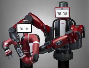
Industrial-standard robotic components, assembled with the most basic simulcrum of a face invites interaction
Robots have a bit of a mixed reputation in the media. One minute they’re vacuum cleaning our homes and delivering our pizzas, the next they’re stealing our jobs and threatening to take over the world.
Thanks to more than 100 years of science fiction books and TV shows, robots remain controversial: they’re either destined to save the planet, or doomed to destroy it.
But how much of this rhetoric is true? With more than 8.6 million robots in existence, and the field of robotics recently being pegged as the “fastest growing industry in the world”, we find ourselves increasingly wondering what this robot-overrun future will look like.
Are robots to be feared, or embraced? More importantly, what is a robot? Should we be counting automated vacuum cleaners and self-service checkouts as part of the new robotics revolution, or are these simply more examples of the ever-expanding internet of things (IoT)?
In an attempt to answer some of these questions, I undertook a review of the most revolutionary robotics developments expected to appear in hospitals, shop floors and workplaces.
The five key predictions for the next five years are outlined below, along with the core challenges they present to the industry, and the areas to watch for the future direction of robotics.
1. Design will bridge the uncanny valley
The so-called ‘uncanny valley’ refers to an aesthetic hypothesis which states that when features look and move almost – but not exactly – like natural beings, the typical response is one of discomfort, or even revulsion.
In response to this hypothesis the production of robotics has focused far more on the development of autonomous machines than on ‘humanoid’ robots.
While it seems unlikely that human beings will ever conquer this response, humanoid aesthetics are nevertheless increasingly vital to the success of many upcoming robotics projects.
As robots increasingly replace workers in a variety of service and social contexts (hospitals and care homes, for example) the need for anthropomorphic features will become increasingly important.
Social technologist Sherry Turkle claims that “a robotic face is an enabler; it encourages us to imagine that robots can put themselves in our place and that we can put ourselves in theirs”.
Based on this growing demand for “lifelike” robots, it is increasingly important that developers overcome the uncanny valley effect.
To achieve this robotic engineers will increasingly turn to semi-humanoid developments, which maintain a traditional machine form, while also boasting very basic – even cartoonish – human features.
A recent example is Baxter, a newly launched robot from Boston-based Rethink Robotics. While Baxter’s body remains a fairly typical production line arm, his interface has been fitted with two motion-sensitive cartoon eyes, which provide just enough identity to press the Darwinian buttons necessary to encourage interaction, without being human enough to trigger the uncanny valley effect.
Such designs will likely be the future of public-facing robotics.
2. Social interaction will replace function
Currently, most consumer-facing robots are designed to be purely functional. From aerial delivery drones through to automated vacuum cleaners, most robots are programmed to serve, not to communicate.
But over the next five years this relationship will begin to evolve, with personal assistant applications such as Apple’s Siri already getting consumers used to the idea of speaking to devices in a naturalistic way.
With similar complex speech-recognition software being adopted across the robotics industry, a rapid shift away from functional machines towards social companions is probable.
Already in 2015 several social robots have been launched. Last month, RoboKind launched Milo, a robotic companion designed to help children with autism develop their social skills.
This year also saw more than $2.2m raised via the crowdfunding site Indiegogo for the development of Jibo, an autonomous ‘helper’ for the family home.
While these developments may seem like works of science fiction, the rise of the IoT has allowed consumer robotics to rapidly become a reality.
With almost 25 billion connected devices in the world, robots like Jibo are now able to function in a social context as a result of their interactions with the connected devices that surround them.
The more items (and ultimately robots) that are added to this network, the more ‘intelligent’ these machines can become.
3. Intelligence will be regulated
Professor Stephen Hawking drew media attention recently after he controversially stated that the development of artificial intelligence (AI) could spell “the end of the human race”.
While many technologists would consider this as nothing more than Luddite fear-mongering, the truth is that Hawking is not alone in his concerns. In fact, both Bill Gates and Elon Musk – hardly technological Luddites – have agreed with the statement, claiming that AI may be “the biggest existential threat” faced by humanity.
As a result there is a growing movement among tech professionals who want to see the development of AI robotics increasingly regulated. In 2009, the Association for the Advancement of Artificial Intelligence (AAAI) held its first conference to discuss whether robots could ever achieve a dangerous degree of autonomy.
More recently, Demis Hassabis – founder of Google’s secretive ‘Deep Mind’ AI project – came together with numerous researchers and industry professionals to develop a ‘Magna Carta for AI’. According to one Google spokesperson, this document was designed to flesh out the ethics governing AI, ultimately making sure that Hawking’s fears are never realised.
While we can’t know for sure how this regulation will be achieved – whether through government intervention or industry-supported standards – what is clear is that artificial intelligence will prove to be a significant point of contention over the next five years.
4. Drones will become de-politicised
One area of robotics that has received widespread interest over the past few years has been the adoption of drones in the consumer and industrial space.
Originally developed for use in military applications, drones have proved a highly controversial topic in the mainstream media. Yet despite the controversy, the past six months have seen a surge in consumer adoption, with radio-controlled drones being offered as everything from bird-watching appliances through to high-end children’s toys.
At the same time, many businesses have begun to consider how drones can be used to improve efficiency in their supply chains and even for home delivery systems.
While many of these applications have represented little more than publicity stunts, the truth is that unmanned drones are already being used in a number of real – and often extremely positive – settings. From providing antibiotics to hospitals in the Himalayas, to delivering university textbooks to students in Sydney, unmanned drones are far more than just a PR gimmick.
As these real life use-cases become increasingly common, drones are likely to become quickly depoliticised in the consumer landscape. While their tricky regulation and original military application may present some difficulties, the potential benefits of unmanned delivery and an increasing number of applications will quickly outweigh such concerns.
5. Cheap hardware will boost ‘makers’
Above all else, the key driving force behind the wider adoption of consumer robotics will be the falling cost of individual hardware components.
This reduction is being driven in part by the popularity of smartphones, with many common robotics components (cameras, sensors, voice recognition) now being mass-produced for use in mobile phones. As a result, the idea of having a personal robot is no longer just the dream of multi-millionaires, but something that will soon become a reality for ordinary people all over the world.
Additionally, according research by Dmitry Grishin, head of Grishin Robotics – the world’s largest venture capital fund devoted solely to developing robots – the future of robotics is also being driven by the growing popularity of low-cost electronics such as the Raspberry Pi and open source Arduino boards. Such low-cost components have led to a revitalisation of the home-robotics movement, with hobbyists being able to build their own autonomous devices for a fraction of past prices.
As reductions in cost help to open up robotics development to a far wider user base and audience a significant boost in the number of robot-focused start-ups is likely over the next five years.
At the same time, however, low-cost circuitry will not necessarily be enough to drive this movement. Adequate power supply is still going to prove a significant issue for consumer robotics, with many robots still struggling with an uneven weight-to-power ratio.
Sadly, while Moore’s law may have helped to significantly reduce the size and cost of internal circuits, batteries and motors still have a long way to go before they can meet the demands that will make consumer robotics a reality.
Simon Holt is marketing manager at element14
Richard Wilson
 An international team has made a transistor from a molecule of phthalocyanine and twelve indium atoms.