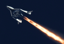
Virgin Galactic SpaceshipTwo
Human error, not mechanical fault, caused the crash of the Virgin Galactic SpaceShipTwo last October, a review has concluded. But the companies behind the craft and the regulator that approved its flight are not off the hook.
The crash was a result of co-pilot Michael Alsbury unlocking the spacecraft’s descent system too early, according to a review conducted by the US National Transportation Safety Board (NTSB) and published on Tuesday.
But Virgin Galactic and Scaled Composites, which built the craft, did not do enough to mitigate the risks of this occurring, and the Federal Aviation Administration (FAA), which issues commercial spaceflight permits, did not pick up on their oversight, the review concludes.
Alsbury was killed in the crash, while pilot Peter Siebold was seriously injured. “We cannot undo what happened, but it is our hope that through this investigation we will find ways to prevent this from happening again,” said NTSB chairman Christopher Hart during an NTSB board meeting in Washington DC earlier today.
Feather wings
SpaceShipTwo is a sub-orbital vehicle designed for tourist flights to the edge of space. As it descends back to Earth, its “feather” wings are meant to rotate upwards to provide drag and slow the craft. Initial analysis of video from the cockpit showed Alsbury unlocking SpaceShipTwo’s wings prior to the crash as it was travelling at 0.92 Mach, just below the speed of sound, not at 1.4 Mach as intended. This meant the wings extended too early and were subject to extreme stress that ultimately led to the break-up of the spacecraft.
So why did Alsbury unlock the wings at the wrong time? The NTSB pointed to a number of contributing factors. Scaled Composites’ hazard analysis did not consider the possibility that pilots would make a mistake during normal flight, only that they might take the wrong action in response to an issue with the vehicle. As such, there were no warnings or limitations on the spacecraft controls to prevent early unlocking.
In May 2013, the FAA told Scaled Composites that it had concerns that its hazard analysis did not meet the requirements for an experimental flight permit. But a few months later, in July 2013, the FAA issued a waiver for these requirements and granted the permit. The NTSB’s investigation found that Scaled Composites did not request this waiver, and some FAA inspectors were unfamiliar with SpaceShipTwo and thought that the requirements had been met.
Virgin Galactic, which has since taken over full responsibility for the vehicle from Scaled Composites, has now modified the spacecraft to prevent the wings from unlocking too early. The company has also modified the flight checklist to warn against unlocking at the wrong time and says that it will post copies of its own submission to the NTSB online later today. “We thank the @NTSB for their professionalism, expertise, and insight, and we welcome the results of their investigation,” said the company in a tweet.
The NTSB proposed eight safety recommendations for the FAA to improve its review processes, including that it should work with private space firms before they start designing their vehicles, not just before they fly, and gave similar recommendations to the spaceflight industry. “Hundreds of people whose only qualification for spaceflight is their ability to purchase a ticket await the opportunity to go into space,” said Hart. “For such flights to proceed safely, commercial space transportation must continue to evolve and mature.”
Syndicated content: Jacob Aron, New Scientist
See also: Firms must explore new aerospace business
See also: Space: Virgin Galactic ship tests its feathering
Alun Williams
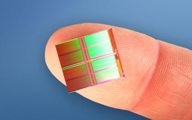
 Plessey has launched a range of LED ‘filaments’ based on GaN-on-Si die made in Plymouth.
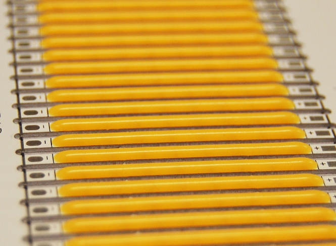 “Plessey will also be incorporating other active and passive electronic components for chip-on-board and chip-scale packaging solutions in next generation of filaments,” said company CTO Dr Keith Strickland.