China and Japan collaborate on exam-passing robot

China and Japan are working together to produce a robot called Torobo-kun capable of passing the University of Tokyo’s entrance exam, reports the Nikkei.

Professor Noriko Arai

Professor Noriko Arai

iFlytek, a Chinese artificial intelligence company, is to work with Japan’s National Institute of Informatics (NII) on the project for which China has a budget of $24.6 million – considerably more than the NII’s budget.

The project to create Torobo-kun started four years ago and, although it is still unable to pass the University of Tokyo’s entrance exam it is reckoned, by Japan’s National Centre for University Entrance Examinations, to have an 80% chance of passing the entrance exams of 80% of universities.

iFlytek approached NII Professor Noriko Arai in May asking if it could join the project. iFlytek heads the Chinese effort which also includes leading Chinese universities.

“China has been closely watching the NII’s project to develop an AI robot, nicknamed “Torobo-kun,” which is capable of passing Todai’s entrance exam,” says Professor Arai who visited China in July to lecture about the project.

david manners

How to meet military EMC regulations

Pete Dorey

Pete Dorey

The European EMC defence standard 59-411 can help with achieving electromagnetic compatibility for COTS military systems, writes Pete Dorey.

The electromagnetic compatibility (EMC) risk assessment process described in Defence Standard 59-411 contains four key steps to assess whether any protection, such as shielding racks and filters, is needed to reduce equipment susceptibility to harsh defence electromagnetic environments and to enhance compatibility with sensitive systems such as military radio.

Define the electromagnetic environment

Once this environment definition is known, the adequacy of the military off-the-shelf/commercial off-the-shelf (MOTS/COTS) EMC performance can be evaluated.

The target electromagnetic environment is usually specified in a User Requirement Document (URD) or System Requirement Document (SRD), and is likely to be one of the default electromagnetic environments described in Def Stan 59-411, such as a ship below-decks environment.

However, it may also be specified for a unique purpose, to ensure compatibility with specified systems, or tailored to a specific environment.

Evaluation of EMC compliance

All non-exempt MOTS/COTS equipment must carry the CE mark of European directives, but its presence alone is not enough to identify levels of EMC performance to which the equipment must comply. This must be identified from the manufacturer’s EU Declaration of Conformity, test report, certificate or specifications.

It is best practice that a copy of the EMC test report or certificate is obtained to confirm the limits applied during testing, in order to ensure the equipment’s suitability for military use. However, obtaining the evidence of EMC compliance is often a major challenge.

Using the guidance in Def Stan 59‑411, a ‘gap analysis’ process can be used to determine whether the MOTS/COTS EMC compliance evidence is more or less stringent than the Def Stan 59-411 test limit. Any shortfalls identified also help to specify the degree of additional protection that is required, such as shielding or filter attenuation.

During this process, it is imperative to identify the test methods and account for them as part of the comparison. This can be a time consuming, costly and complex exercise, so the use of specifically designed gap analysis tools is recommended.

Functional criticality

The risks identified during the gap analysis process must now be compared to the criticality of the equipment and platform environment impact in which the COTS/MOTS equipment will be used.

If any unacceptable risks are identified, they must be mitigated. For example, if the equipment has a critical function itself, adequate immunity is required. If the equipment is co-located with other sensitive critical equipment, adequate emission control is required.

Once the functional criticality process has determined the unacceptable risks, they must then be mitigated.

Mitigation of unacceptable risk

There are two options for risk mitigation, either:

• Retest the MOTS/COTS equipment to determine compliance with Def Stan 59-411. This is technically a good approach, as any additional protection can be properly specified and over‑protection will be avoided. However, the disadvantage is the cost of the additional required testing.

• Remedial re-design can be achieved by adding the appropriate protection ‘barriers’ to reduce the coupled RF fields or currents that the equipment could be exposed to, or could emit, to below the levels it was originally required to meet.

Many manufacturers now offer suitable RF shielded racks and enclosures for this purpose, which allow the MOTS/COTS equipment to be housed without modification therefore preserving the validity of its CE marking. Additional filters and transient protection can also be accommodated within the enclosure. If the equipment itself is modified to achieve EMC, it is considered to have become ‘modified off the shelf’ equipment and needs to meet the EMC Directive with CE marking as a ‘new apparatus’ in its own right.

Something that could be overlooked is that the current UK EMC regulations (SI 2006 No.3418) implementing the EMC Directive 2004/108/EC do not have a specific exemption for defence equipment, whereas the previous regulations did, under Article 346 of the Treaty of the European Community.

This has led to some confusion among designers and manufacturers, with some presuming that a ‘blanket’ exemption applies to military equipment.

However, the applicability of CE marking to military equipment was clarified by the European Commission in April 2012 with the statement: “Equipment which falls within the scope of the Radio & Telecommunications Terminal Equipment Directive, EMC Directive or Low Voltage Directive, shall be compliant with the applicable Directive(s) and bear CE marking.”

Defence contractors must therefore ensure that any manufacturers or suppliers they use understand and comply with these rules.

Member states can exclude defence equipment from the scope of European Union procurement regulations and Directives pursuant to Article 346 (ex.296) of the Treaty on the Functioning of the European Union on the basis of the protection of national security interests.

This is not a decision for the manufacturer. Further guidance on the compliance of military equipment with the EMC Directive was published by CENELEC in report TR50538 in 2010.

In April 2016, a new EMC Directive 2014/30/EU and EMC Regulations will come into force, but do not affect the requirement for military equipment. Applying the EMC Directive to defence equipment requires careful management to avoid unnecessary duplication of compliance-testing – once for Def Stan 59-411 and once for CE marking, which will incur additional costs.

However, testing can be minimised by using the gap analysis process to establish in the technical documentation the equivalence between Def Stan 59-411 and the MOTS/COTS standards. This in itself can be a time consuming and costly exercise and often takes users away from their core expertise or comfort zone.

Due to the complexity of performing gap analysis, such a partner could offer a low risk, and ultimately low cost solution to deal with defence EMC requirements. It will ensure that the resulting products are legally placed on the market and acceptable for delivery, particularly for high-value projects.

Writer is Pete Dorey, a principal EMC consultant at product testing and certification organisation, TÜV SÜD Product Service

Richard Wilson

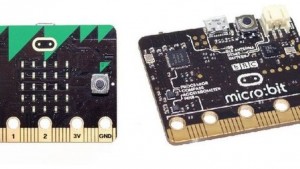
BBC Micro:bit computer delayed

BBC Micro:bit computer

BBC Micro:bit computer

The BBC Micro:bit computer, due to be given to a million schoolchildren in October, will be delayed until the New Year, says the BBC.

Up to one million Year 7 pupils (aged 11 and 12) are due to be given the tiny computer to help them learn how to code.

“We’re expecting to start sending them out to teachers before Christmas and to children early in the new year,” said a BBC spokesman, “as a result of our rigorous testing process, we’ve decided to make some minor revisions to the device – getting it right for children and teachers before we manufacture one million units is our priority.”

The problem relates to the power supply and only affects a “small number of devices.”

29 partners including Barclays, Microsoft, Samsung and Lancaster University are involved in Micro:bit and product champions, including Cisco, Code Club and Teen Tech, are proving educational resources.

See alsoMicro:bit reunites BBC and ARM for grand education initiative


david manners

SEMI b-to-b positive in August

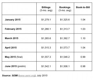
The SEMI August book-to-bill ratio was 1.06.image

Bookings were $1.67 billion which were 5% up on July and 23.8% up on August 2014.

Billings were $1.58 billion which was 1.3% above the July billings and 21.9% higher than August 2014.

“Given the trends through the year so far, the book-to-bill ratio stayed above parity on a three-month average basis,” says SEMI CEO Denny McGuirk, “an adjustment in the trends is anticipated for the rest of the year due to the near-term economic outlook and lower demand for electronics in some sectors.”

The last six months book-to-bill ratios were:

March 1.10

April 1.04

May 0.99

June 0.98

July 1.02

August 1.06

SEMI tracks a total of 43 new and continuous construction projects in 2015 with investment totalling over $5.9 billion.

See alsoQ2 bookings surge, reports SEMI

See alsoFront end equipment spending up 5% this year, 6.6% next year

Read more SEMI stories on Electronics Weekly »

david manners

Rohm tackles USB Type-C power

Rohm USB Type-C power

Rohm USB Type-C power

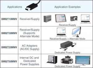
ROHM has developed power receiver controller ICs compatible with USB Power Delivery (Rev2.0) and Type-C (Rev1.1).

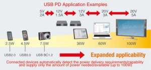
BM92TxxMWV series supports conventional USB power up to 7.5W, all the way up to 100W (20V 5A) for USB Type-C connected devices.

“This will make it possible to drive equipment with larger power requirements such as TVs and PCs via USB and at the same time enable conventional USB-equipped portable devices – smartphones and tablets – to be charged up to four times faster than the previous standard,” said Rohm.

“The latest USB connector and power transmission standards developed by USB-IF [USB Implementers Forum], which includes USB Type-C, USB Power Delivery, USB Superspeed and the new DisplayPort Alternate Mode standard for carrying video, are garnering increased attention as a true all-in-one cable solution by making it possible to deliver high power, high-speed data, and even 4K video simultaneously over a single USB cable/port. This will eliminate the need for dedicated cables, providing greater convenience while reducing clutter and waste.”

Rohm USB Type-C product lineThe firm has used a 0.13um BiCDMOS processes for its IC, eliminating the need for an external fet and it power supply.

For the Power Deliver standard, optimum power delivery is enabled in both directions along a USB Type-C connection through a power contract that determines the Provider (Supply) and Consumer (Receiver) devices.

The Consumer only requests the required amount of power and the Provider only supplies the power available.

Power delivery scales from 7.5W (5V 1.5A) up to 100W (20V5A) – see diagram.

DisplayPort Alternate Mode carries video signals over USB, eliminating the need for dedicated video cables.

Price is $16.5/unit, and the chip is sampling this month with OWM quantities expected in December.

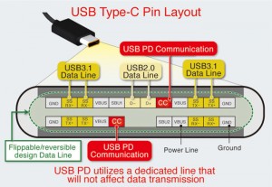
USB Type-C layout - from RohmUSB Type-C

Defined under USB3.1, USB Type-C is a receptacle (concave connector), plug (convex connector), and cable standard.

Cables are reversible and flippable – so the connector fits either way around and the ends can be swapped too.

Power requirements are negotiated between connected devices to determine the upstream and downstream facing ports (UFP and DFP), providing greater convenience and utility.

steve bush

Freescale replaces traditional car batteries with Li-ion

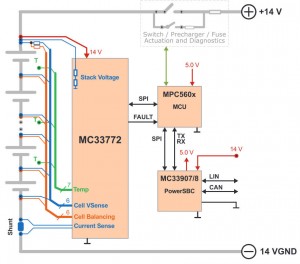
Freescale MC33772Freescale Semiconductor has announced a lithium-ion cell controller with performance and functional safety features optimised for 14V car batteries, intended to replace traditional Pb-acid automotive batteries.

“Lead-acid automotive batteries are increasingly being replaced by Li-ion chemistries to reduce weight, increase reliability and boost energy efficiency for engine start-stop systems and energy recuperation technologies,” said the firm. “Recent advances in Li-ion battery chemistry for cold temperature operation and cold cranking power now enable Li-ion batteries to displace lead-acid even as the starter battery.”

While Pb-acid batteries are heavy,  it is one of the battery technologies least likely to explode or bust into flames.

In contrast, many Li-ion chemistries are flammable, requiring close monitoring, and all of them need tight control of charge voltage to balance life with energy density.

“To maintain safe operating conditions and ensure system-wide control of the battery, battery cell controllers must provide accurate, reliable battery diagnostics and high speed communication of status,” said Freescale.

The chip, called MC33772, includes functional verification supporting ISO 26262 ASIL-C requirements, which help protect automotive batteries against critical fault conditions. ASIL-D (higher level) system implementations be realised using multiple Freescale battery cell controllers for redundancy. For functional safety design to ISO 26262 and IEC 61508, the chip is supported by Freescale’s SafeAssure programme.

It supports 2Mbit/s battery health and conditions communication for centralised, distributed CAN and distributed daisy chain battery management system topologies.

Freescale points out its battery controller portfoilio includes support for: lithium iron phosphate, lithium nickel manganese cobalt oxide, lithium titanate and lithium polymer cells, but it is not yet clear if the MC33772 can work with all of these.

MC33772 at a glance

  • AEC-Q100 automotive qualified
  • 3, 4, 5 and 6 cell versions
  • SPI direct-coupled communication
  • 2MHz isolated  TPL (transformer physical layer) communication using separate chip (MC33664)
  • 5-30V operation, 40V transient (7-30V with TPL comms)
  • Current sensor with ±0.5% accuracy from mA to kA
  • 6x differential cell voltage measurement and stack voltage measurement
  • Synchronised cell voltage/current measurement
  • Coulomb counting
  • 7x ADC/GPIO/temperature sensor inputs
  • Addressable on initialisation
  • 6x onboard 300mA passive cell balance drivers with timers
  • Low-power modes
  • 48pin QFP
  • Products are sampling now, with production planned by Q2 2016.

Evaluation kits KIT33772ASP1EVB and KIT33664EVB support the MC33772 and MC33664 transformer physical layer.

Conventional Li-ion cells cannot safely be charged at all at temperatures below 0C, and discharge power is severely limited – see this article at Cadex’s Battery University.

steve bush