The proliferation of wireless sensors will increase the demand for efficient power converters suitable for low voltage requirements of energy harvesting systems, such as wearable sensors, writes Tony Armstrong of Linear Technology
Energy harvesting technologies are looking particularly interesting when applied to wearable electronic devices.
Soon there will be wearable fabrics that can generate electricity from different forms of ambient energy that might only require a small primary battery as a back-up source.
These free energy sources include body temperature generation, photovoltaic sources such as indoor lighting or even just plain old daylight, as well as kinetic energy sourced from regular body movements.
A European Union-funded research project called Dephotex has developed methods to make photovoltaic material light (as in weight) and flexible enough to be worn.
Naturally, the material will convert photons into electrical energy, which in-turn can be used to power various electronic devices worn by the user, or to charge their primary batteries, or even a combination of both.
At the low end of the power spectrum there are nanopower conversion requirements for energy harvesting systems which require power conversion ICs that deal in very low levels of power and current. These can be tens of microwatts and nanoamps of current, respectively.
For example in vibration energy harvesting and indoor or wearable photovoltaic cells, yield power levels in the order of milliwatts under typical operating conditions. While such power levels may appear restrictive, the operation of harvesting elements over a number of years can mean that the technologies are broadly comparable to long-life primary batteries, both in terms of energy provision and the cost per energy unit provided.
Moreover, systems incorporating energy harvesting will typically be capable of recharging after depletion, something that systems powered only by primary battery cannot do. Nevertheless, most implementations will use an ambient energy source as the primary power source, but will supplement it with a primary battery that can be switched in if the ambient energy source goes away or is disrupted.
The energy provided by a typical energy harvesting source depends on how long the source is in operation. Therefore, the primary metric for comparison of scavenged sources is power density, not energy density.
Energy harvesting is generally subject to low, variable and unpredictable levels of available power so a hybrid structure that interfaces to the harvester and a secondary power source is often used. The secondary source could be a re-chargeable battery or a storage capacitor (maybe even supercapacitors).
The harvester is the energy source of the system. The secondary power reservoir, either a battery or a capacitor, yields higher output power but stores less energy, supplying power when required but otherwise regularly receiving charge from the harvester.
When there is no ambient energy from which to harvest power, the secondary power reservoir must be used to power the down-stream electronic systems.
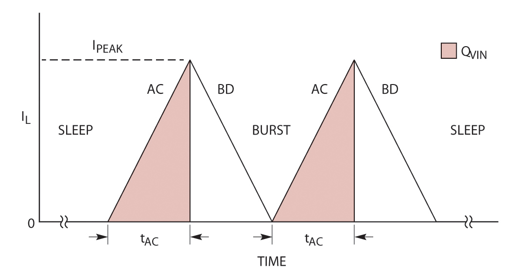
Figure 2: Timing diagram
An example device for this type of application is the LTC3331 which integrates a high voltage energy harvesting power supply with a synchronous buck-boost DC-DC converter powered from a rechargeable primary cell battery. This can be used as a single non-interruptible output for energy harvesting wearables and wireless sensor nodes (WSNs).
The energy harvesting power supply, consisting of a full-wave bridge rectifier accommodating AC or DC inputs and a high efficiency synchronous buck converter, harvests energy from piezoelectric (AC), solar (DC) or magnetic (AC) sources.
The LTC3331 requires no supply current from the battery when providing regulated power to the load from harvested energy and only 950nA operating when powered from the battery under no-load conditions.
A 10mA shunt enables simple charging of the battery with harvested energy while a low battery disconnect function protects the battery from deep discharge. The rechargeable battery powers a synchronous buck-boost converter that operates from 1.8V to 5.5V at its input and is used when harvested energy is not available to regulate the output whether the input is above, below or equal to the output.
A control feature means the charger will only charge the battery when the energy harvested supply has excess energy. Without this logical function the energy harvested source would get stuck at startup at some non-optimal operating point and not be able to power the intended application through its startup.
The very low energy and current levels in typical wearable devices mean that to use a DC-DC converter it must consume current in the order of nanoamps.
For example, the LTC3335 has a quiescent current of 680nA. Its design incorporates a coulomb counter which monitors accumulated battery discharge. This counter stores the accumulated battery discharge in an internal register accessible via an I2C interface. The buck-boost converter can operate down to 1.8V on its input and provides eight pin-selectable output voltages with up to 50mA of output current.
To accommodate different battery types, the peak input current can be selected from as low as 5mA to as high as 250mA and the full-scale coulomb counter has a programmable range of 32,768:1.
Its integrated precision coulomb counter monitors the accumulated charge that is transferred from a battery whenever the buck-boost converter is delivering current to the load. The buck-boost converter operates as an H-Bridge for all battery and output voltage conditions when not in sleep mode (see Figure 2).
Switch A and C turn on at the beginning of each burst cycle. The inductor current ramps to Ipeak and then switches A and C turn off.
Switches B and D then turn on until the inductor current ramps to zero. The cycle repeats until Vout reaches the sleep threshold.
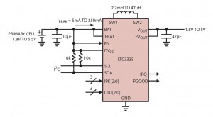
Figure 1: Schematic for nanopower converter circuit
If Ipeak and the switch AC(ON) time (tAC) are both known, then the BAT discharge coulombs (shaded area in Figure 2) can be calculated by counting the number of AC(ON) cycles and multiplying by the charge per AC(ON) given in the formula below:
q AC(ON) = (Ipeak x tAC)/2
When the buck-boost is operating, the LTC3335 measures the actual AC(ON) time relative to the full scale ON time (tFS, approximately 11.74µs) which is internally adjusted to compensate for errors in the actual selected Ipeak value due to supply, temperature and process variations. This results in a useful assessment of the charge transferred from the battery during each AC(ON) cycle.
Tony Armstrong is director of power product marketing, Linear Technology
Richard Wilson