Author Archives: steve bush

Chip offers accurate Doherty balance on-the-fly

Perigrine MPACTo take the pain out of Doherty amplifier balancing, Peregrine Semiconductor is planning to introduce a single-chip dual-channel amplitude and phase adjuster.

Doherty amplifiers have two RF amplifiers in parallel (see diagram), one Class-AB for low-level signals and one Class-C for peaks. They save power over single amplifiers that can handle high peak-to-average signals, like those of LTE (8dB) and LTE-Advanced, with sufficient linearity.

Signals going into the two amplifiers have to be adjusted carefully to ensure their outputs combine to create the correct antenna feed.

The firm is aiming its chip at macro and small cell base stations.

“The current solution employs discrete components to tune phase and amplitude for carrier and peaking paths,” said Peregrine, which concedes Freescale is also aiming to replace discretes, this time with a system-in-package containing three GaAs and one CMOS die.

Made on a 0.35µm silicon-on-sapphire process, Peregrine’s PE46120 monolithic phase and amplitude controller (MPAC) includes: a 90°hybrid splitter, two phase shifters, two amplitude controllers, and an SPI digital interface.

Both paths can be optimised on-the-fly through the SPI interface to compensate for operational or environmental changes. Switching time is 840ns.

The firm has based the design on existing products, using switches and passive components on-die. Phase shifting is through combined low-pass and high-pass filters. “It is more of an RFIC approach, said Mark Moffat, MD Peregrine UK. “For an X band product [which is mooted], we would probably use more of a MMIC approach.”

Insertion loss is 6.5dB including the 3dB splitter, and operation is from 1.8 to 2.2GHz in 5.6° steps across an 84.4° range, as well as 0.5dB steps across 7.5dB range. Linearity is 65dBm IIP3, return loss 20dB, isolation 28dB, and maximum power 29dBm.

The chip will run off 2.7-5.5V (at 300µA), and over -40 to 105°C.

It comes in a 6x6mm 32 lead QFN, and needs no external dc blocking capacitors.

Other applications proposed are: micro and pico cells (10W and above), electronically-steered radar, and synthetic aperture radar.

Three other versions are in the pipeline: 2.4-2.8GHz, 700MHz-1GHz, and one for LTA-A bands.

At the same time as announcing the intention to introduce the Doherty chip, Peregrine also revealed what it claims are the first monolithic 50W power limiters.

Power handling is +47dBm (50W) pulsed, +40dBm (10W) CW.

PE45140 (20MHz-2GHz) and PE45450 (9kHz-6GHz) are intended as an alternative to discrete GaAs PIN-diode limiters in ‘land mobile radio’ (LMR), test-and-measurement, wireless-infrastructure and radar.

Linearity (IIP3) is over 40dB and limiting threshold can be as low as 22dBm and as high as 35dBm.

Response-and-recovery is under 1ns.

There are two modes: power limiting and power reflecting, with threshold selectable through an analogue control pin voltage.

For example, in limiting mode (Vcontrol = -2.5 to -0.5V) PE45140 performs as a linear power limiter with adjustable P1dB / limiting threshold.

Power reflecting mode requires an external power detector to sample the RF input power and a microcontroller to toggle the limiter control voltage between +2.5V and -2.5V. At +2.5V, limiter impedance to ground is less than 1Ω and most incident power will be reflected back to the source. At -2.5V, the device operates as in power limiting mode.

Package is 3x3mm 12 lead QFN

£1.18m MoD ship order for Gresham

Tide class tanker Crown copyright MoDGresham Power Electronics of Wiltshire has secured a £1.18m order from Korea based Daewoo Shipbuilding and Marine Engineering (DSME) to supply un-interruptable power supply (UPS) systems for the Royal Fleet Auxiliary’s Tide class tankers, currently being built by Daewoo.

To be delivered to the MoD, each tanker requires eight UPS systems of various power ratings.

“After nine months of hard work by us and our Korean partner C&A Electric we are very pleased to have secured this important contract,” said Gresham MD Jake Moir. “This order will be a major part of our forward order book for the next two years and provide us with a platform to develop new products. Our defence business continues to grow and we now have export customers in markets that include Spain, France, Australia, India and now Korea.”

Jake Moir MD Gresham Power

Jake Moir

DSME is building four tankers to support Type 45 Destroyers at sea supplying, amongst other things: fuel, food, fresh water and ammunition.

Gresham also provides power products built into Type 45s, Type 23 Frigates, and the two Queen Elizabeth class aircraft carriers.

The 200m long 37,000 tonne Tide-class ships (means their names will begin with ‘Tide’), formerly known by the MoD as ‘Mars’ tankers, will come into service from 2016, and will also be able to carry helicopters.

Tide class ships are double hulled – one inside the other rather than catamaran. Previous Royal Fleet Auxiliary tankers, also ‘Tides’ were single-hulled and liable to spill oil if punctured.


Imagination aims radio IP at IoT

Iimagination Ensigma Whisper radioImagination Technologies has introduced wireless intellectual property for internet-of-things devices.

Branded ‘Whisper’, it is part of Imagination’s Ensigma Series4 low-power radio processing unit (RPU) family.

“With our existing Ensigma RPUs, customers are already building a range of life-style devices,” said Imagination marketing v-p Tony King-Smith. “With Whisper RPUs, customers can create devices targeting markets as diverse as eHealth, energy, agriculture and security.”

The new architecture supports “lower” bitrate connectivity standards, said Imagination, which will start to roll out the cores in Q4 2014.


More on: Infineon’s over-current blocking FET

Infineon ocb fet

Over-current blocking fet

Infineon Technologies is to develop a two-terminal semiconductor device that acts as a circuit breaker for hundreds of volts and amps: doubling the performance of its mains-voltage super-junction mosfets along the way.

The aim is to replace electromechanical circuit breakers with something faster.

“A circuit breaker can take up to 8ms to switch off current. Even 5ms is far too much for a Li-ion battery,” Dr Anton Mauder, project leader for high-voltage power device development at Infineon, told Electronics Weekly.

Mauder is also technical head of ‘NEST-DC’, a consortium consisting of Airbus, E-T-A, Infineon, Siemens, and the University of Bremen which, with German Government funding, aims to exploit the device, which is known over-current blocking field effect transistor (OCB-FET).

Airbus is in there because it wants fast circuit breakers for aircraft dc power grids. Photovoltaics are another potential application, as are electric cars.

The basic device is based on an idea by Dieter Silber and his group at the University of Bremen.

It uses depletion-mode jfets.

Depletion-mode jfets, such as the n-channel device in figure 1, are naturally ‘on’ and need a negative gate voltage (with respect to the source) to turn them off.

Infineon ocb fet

Fig1: Jfet constant current

In figure 1, the transistor is in the classic constant current configuration where negative feedback from the resistor voltage drop and gate threshold voltage (Vth) cause the channel to regulate through-current to a reasonably constant value.

Silber’s device takes this a step further.

He put a p-channel jfet in place of the resistor (see figure 2).

In this configuration, the channel on-resistance of each jfet acts at the sense resistance for the other’s gate.

When current is flowing from top to bottom, it sees a purely ohmic conduction path consisting of the two channels in series.

Until that is, current reaches the point where one channel voltage drop reaches the Vth of the other jfet – say T2. At this point T2 starts to turn off, which causes the gate voltage of the p-channel jfet T1 to rise, which turns it off. This positive feedback turns both devices off completely in a few µs, and conduction cannot re-start until the power source is removed.

Which fet turns off first depends on the mix of threshold voltages and channel resistances. Fine tuning of these parameters, with due consideration to temperature, allows the trip current to be set – or rather, to set the minimum current that always passes, and the minimum current that never passes.

“At the threshold, the structure quenches, it pinches-off,” said Mauder. “You need very steep resistance after limit. This is an issue for basic structure. We could also use two depletion mosfets. We are investigating if mosfets or jfets are best. The environmental temperature is important.”

Infineon ocb fet

Fig2: Jfet current block, or ‘lambda diode’

As an aside: this structure conducts backwards, but without the over-current blocking characteristic. When conducting forwards with regulated current or voltage, a well-defined negative resistance region can be measured. This negative resistance was once used in RF oscillators, where the pair was called a ‘lambda diode’.

Although this structure could work at hundreds of amps – it just has to have large junctions – there are two reasons it is not viable at hundreds of volts: firstly, the gates would have to withstand the full blocking voltage – close to a show-stopper for devices handling over 20V. Secondly, high-voltage junctions are far larger than low-voltage junctions. “For good conductivity, you have to have low RDSon,” said Mauder. “For the same RDSon, the area of a high-voltage mosfet is proportional to (voltage blocking)2.5 to V2.6.”

Silber at the University of Bremen originally conceived this structure as the low-voltage control element in a high-voltage transistor related to IGBTs.

IGBTs are great for silicon area as for a given blocking voltage they are far smaller than mosfets.

However, for the NEST-DC consortium, IGBTs have a fundamental limitation: heat dissipation.

“An IGBT always has p-n junction, and for silicon this will drop 0.7V. In reality, they hardly ever get below 1V,” said Mauder.

However big its junction is, if the current limiter has an 0.7V drop and is passing 100A, it is going to dissipate 70W. This means it will need a lot of room around it, and will put a significant dent in the efficiency of the system of which it is part.

“For our OCB fet, we want it to be ohmic, to have no 0.7V knee voltage,” said Mauder. So the high-voltage element has to be a jfet or a mosfet, and dissipation can now be arbitrarily low, as long as the fet channel is big enough – which is not such a big problem as fighting the V2.5 issue mentioned above – more of this later.

Infineon ocb fet

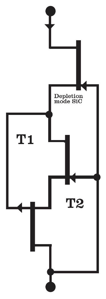
Fig3: Cascode allows a low voltage mosfet to switch high voltage via a jfet

Mauder is proposing to use a cascode structure – see figure 3.

Originally proposed as a way to improve the bandwidth of RF amplifiers, cascode switching has really caught on in power circuits since GaN ‘hemt’ and SiC jfet power devices have appeared – both of which are depletion-mode in nature.

With a cascode, a high-voltage depletion-mode GaN or SiC transistor can be turned on and off by a far smaller low-voltage enhancement-mode silicon mosfet.

When the mosfet in Figure 3 is turned off by a control signal that pulls its gate to ground, the source voltage of the high-voltage SiC JFET rises and the JFET turns off because its gate is now negative with respect to its source.

The Si mosfet has to carry the same current as the high-voltage device, but it can be far smaller because the maximum voltage across it is the Vth of the depletion-mode transistor, seldom above 20V.

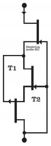
Infineon’s proposed structure replaces the cascoded low-voltage Si mosfet with the double jfet current limit – see figure 4.

Full device current still flows through the jfets but, like the cascode Si mosfet, only have to withstand the Vth of the high-voltage transistor and so can be two small low-voltage jfets.

Infineon ocb fet

Fig4: Over-current blocking fet

The high-voltage transistor still needs a large area, but that is one large junction rather than two – with no gate voltage problems. And, for a given blocking voltage, both SiC and GaN transistors are smaller than their Si cousins, which is why the V^2.5 area issue diminishes. Infineon makes SiC jfets up to 1,700V.

This is a lightning-fast device and, particularly as electronic loads tend to have capacitive inputs, might get tripped-out by switch-on surges.

“There are certain strategies being investigated by partners to do filtering on this basic idea so very short transients do not trip the safety device immediately – for example some RC on the gate [in figure 4]“, said Mauder.

The whole device is a self-contained two-terminal component that does not need an external power supply and has no other inputs through which it might be damaged by external failures – which are reasons Infineon didn’t go the obvious route and combine an existing high-voltage transistor with a sense resistor and a comparator.

“Not needing any external supply for me is big advantage. What happens if the auxiliary supply fails? – Either you get uncontrolled current flow or it disconnects. We are able to do over-current turn-off without need of external current measurement,” said Mauder.

However, if more than two terminals can be accepted, Mauder has another trick up his sleeve.

SiC and GaN transistors are made on expensive processes. Could the high-voltage transistor be a simple silicon mosfet, which would also allow the whole OCB FET to be monolithically integrated?

Infineon popularised the ‘super-junction’ mosfet when it introduced its first CoolMOS branded devices. Super-junction transistors use a structural trick to reduce die area more than is possible with conventional high-voltage mosfets.

A second branch of NEST-DC is a project to further improve super-junction mosfets so they can be used to replace the SiC jfet in figure 4.

“We are investigating a new way for super-junction devices to reduce RDSon x area. State-of-the-art is 6.2Ωmm2 or even more, and we want to considerably reduce this value and chip area,” said Mauder.

Some simulations have already been done and show it is possible. “Now we have to have a closer look via simulation and experimentation. We need to retain ruggedness and avalanche capability. I have good feeling we can do that,” he said.

However, super-junction mosfets are enhancement-mode devices, so an all-silicon version would need an auxiliary supply.

“Since there is no frequent switching needed, this auxiliary supply might be a super-capacitor or something similar which could supply the gate of the high-voltage enhancement MOS over pretty long time – hours or even for days,” said Mauder.

And once an auxiliary supply is accepted, the current limit can become a switch as well as a breaker.

“In most applications, a remote access to such a safety switch is wanted anyway to use it as a conventional switching element. One could use this access to turn-on and turn-off the safety switch via charging or discharging the super-cap auxiliary supply,” said Mauder. “In case of a failure of the remote access, the safety switch still has its stand-alone capability to respond to overcurrent without additional devices or additional supply voltages [if the super-cap is charged].”


Google offers $1m power inverter challenge

Google little box challenge

Google little box challenge

Google, together with the IEEE, is offering $1m to the person or team who best shrinks the size of power inverters, in something called the ‘Little box challenge‘.

“We’re looking for someone to build a kW-scale inverter with a power density greater than 50W/inch3,” said the firm, which is suggesting wide bandgap semiconductors (GaN or SiC, for example) could be part of the answer.

As such, it has teamed up with SiC and GaN vendors: Cree, Efficient Power Conversion, GaN Systems, Monolithic Semiconductor, NXP, Rohn, Transphorm, and United Silicon Carbide.

A test facility will be set up in the US to evaluate potential winners.

The competition is open worldwide to anyone, individuals, teams, companies, and academics. For the latter, grants of around $25,000 are available from Google.

Timetable:

  • Registration by 30 Sep 2014
  • Submit approach by 22 Jul 2015
  • Final date for testing 21 Oct 2015.
  • Winner announced Jan 2016

Google is not requiring any intellectual property or licenses be granted, except a non-exclusive license to be used only for the purpose of testing the inverter and publicising the prize.

CadSoft launches v7 of Eagle PCB

CadSoft Eagle v7

CadSoft Eagle v7

CadSoft has rolled its Eagle PCB layout tool to version 7, improving the auto-router and allowing large designs to be split across a team.

The auto-router can simultaneously generate multiple routing variants on multi-core processors (one per core) and requires fewer manual interventions.

Large schematic designs to be organised into a hierarchy of small functional blocks which can thn be assigned to different team members, while “giving large organisations a global view of the functional blocks of the project to make it easier to locate and change aspects of the schematic or layout”, said CadSoft.

There have been changes to licencing. Users now need to specify the identity number (HostID) of the computer they are running Eagle on when they buy it. Multi-user licensees will manage seats from a license server. Single-user licensees can install their software on up to two devices.

There is also a tool (one of CadSoft’s .ulp ‘user language programs’) to export .idf (intermediate data format) files representing the maximum rectangular dimension of components (see image). These place-holders can be used for preliminary mechanical checking before exact 3d models are available.

“A comprehensive 3D model can be created with Simplified Solution’s ‘IDF-to-3d’ tool,” said the firm, which will be offering IDF-to-3D in its web shop later in the summer.

News 2014-07-15 09:02:10

LG 18inch rollable displayLG Display has developed an 18inch flexible OLED display, and another one that is flat, but transparent.

The flexible display has 1,200×810 resolution and can be rolled around a 60mm cylinder while working – made possible in part by using a polyimide film substrate and organic thin-film transistors.

“This proves that LG Display can bring rollable TVs of more than 50inch to the market in the future,” said the firm.

LG transparent displayThe transparent 18inch OLED has 30% transmittance and LG has “lowered the haze of the panel to a level of 2%,” it said. “Considering that the transmittance of existing transparent LCD panels is around 10%, this panel offers significantly improved transmittance.”

By 2017 the firm believes it will have an “Ultra HD” flexible and transparent OLED panel of over 60inch with more than 40% transmittance and a minimum curve diameter of 200mm.

More on: Raspberry Pi Model B+

Raspberry Pi Model B+The Raspberry Pi Foundation has up-graded the Raspberry Pi Model B but, for industrial users, “we’ll be keeping Model B in production for as long as there’s demand for it”, said the Foundation’s Eben Upton.

The new board is the Model B+, which should not be thought of as a Raspberry Pi 2, added Upton.

What is different?

  • GPIO header extended to 40 pins. First 26 pins exactly the same as 26 pin header on original.
  • Two extra USB ports bringing total to four.
  • SD Card socket is now a Micro SD Card socket.
  • On-board regulators are now switchers, saving from 0.5 to 1W.
  • Lower power consumption. By replacing linear regulators with switching ones we’ve reduced power consumption by between 0.5W and 1W.More USB. We now have 4 USB 2.0 ports, compared to 2 on the Model B, and .
  • Composite video now emerges from a fourth pin on the 3.5mm audio jack.
  • The connectors have bene moved to put them along two sides of the Pi, not all four.
  • There are now four mounting holes, and the board corners have been rounded.

Raspberry Pi Model B+ pinout

What is the same?

  • The SoC remains the Broadcom BCM2835 (ARM11 v6 archtecture).
  • RAM is 512Mbyte
  • Model B software runs on the B+
  • element 14 and RS are suppliers
  • Camera (CSI) and display (DSI) connectors stay

The power supply clean-up extends to “better hotplug and overcurrent behaviour” on the USB, said Upton, and “the audio circuit incorporates a dedicated low-noise power supply”.

Extensions to the IO include ID-SC and ID-SD which form an I2C bus for external EEPROM so boards plugged into the 40pin header can identify themselves to allow the IO to be configured by the ARM processor.

More on: Toshiba supplies UK with 1MW smart grid battery

Toshiba Sheffield lithium ionThe University of Sheffield is building a 2MW 1MWh smart grid energy store, using novel lithium ion batteries from Toshiba. It will be the UK’s largest grid-connected battery.

Funded by the EPSRC, the store will be a research facility for academics and power companies, and the biggest in the UK.

Is purpose it two-fold: power companies can study the use of energy storage on the grid, and it will allow lithium titanate (LiTiO), a relatively new Li-ion material championed by Toshiba, to be evaluated.

LiTiO cells have a longer life than any other Li-ion chemistry, project leader Professor David Stone told Electronics Weekly. And they can be charged far faster than phone batteries.

Toshiba claims over 10,000 cycles (to 20% lost capacity), six minutes to 80% charged, and 15 mins to full chage for the SCiB-branded cells selected by Sheffield. Energy density is 90Wh/kg and 177Wh/litre.

The UK facility is being built at a sub-station near Wolverhampton, owned by project supporter WPD. Aston University is another project partner.

Nishi-Sendai sub-station Toshiba Tohoku Electric PowerAlthough it will be the largest in the UK, there are several of similar size grid batteries around the world, and a 40MW 20MWh SCiB battery is due to be operating at Nishi-Sendai sub-station in Japan in 2018.

For its installation, Sheffield is buying-in a 2MW bi-directional converter from ABB to match the 800V battery to an 11kV power line,

Toshiba is providing the low-level cell and battery monitoring electronics, while Stone’s team and Toshiba are developing the controller that sits between low-level monitoring and the converter.

Experiments are not yet funded, although discussions with electricity suppliers have started.

According to Stone, control strategies for such a battery can be as simple as locally keeping the substation voltage or frequency within specified limits. Remote control will also be possible to allow the national grid to pull its strings.

With a statistically-significant number of cells in the system, experiments could include determining what effects power demand has on the cells and cell balancing, said Stone, as well as how much stabilisation is possible form such a battery, and discovering if there really are business opportunities around grid stabilisation.

Up and running by the end of October, this will only ever be a research tool, said Stone, estimating that the smallest commercial battery would need to deliver 10MW and store 10-20MWh.

Toshiba’s lithium titanate batteries

SCiB batteries are already used in four Japanese grid storage projects, excluding Nishi-Sendai, as well as in two Mitsubishi electric cars and a Honda electric motorbike.

They are built around a 115x103x22mm 20Ah (0.2C) cell for which Toshiba has built a factory with 6GWh/year capacity.

Cell voltage is 2.3V nominal and 1.5-2.7V operating, and internal impedance is 530µΩ.

Continuous discharge is up to 160A, and is “nearly equivalent to ultra-capacitors”, says Toshiba. Discharge is possible from -30 to +55°C.

Charging temperature information is so easy to come by. Automotive versions have been demonstrated charging at 1C at -40°C. Standard laptop Li-ion cells cannot be charged below 0°C.

Unlike laptop cells, they can be crushed with only a low risk of thermal run-away.

The firm takes a modular approach to supplying cells and batteries:

  • 24 cells are packed into a 1.1kWh module.
  • 22 modules go into a 24kW rack
  • 84 racks go into a 1MW 2MWh battery, which occupies 110m2 including switch gear.


At module level, voltage and temperature data is provided to the controller over a CAN bus.

Two terminal Hall sensor has error correction

Allegro A1688 mechanical arrangementThere is a lot going on inside Allegro’s latest two-terminal Hall-effect detector.

Not only is there DSP alongside the chip’s sensors, but a co-packaged supply capacitor too.

Aimed at sensing fast-rotating small diameter wheels, and called A1688, “the device contains a sophisticated digital circuit that reduces magnet and system offsets, calibrates the gain for air-gap-independent switch-points, and provides true zero-speed operation,” said the firm.

Allegro A1688 block diagOffset and gain-adjust is done at power-up, and calibration continues during operation to protect the output from what Allegro describes as “micro-oscillations of the sensed target”, as well as changes in the air-gap.

Sensing is through two Hall elements (1.75mm apart) and processing is differential. The device works with magnetic encoders, or non-magnetised ferromagnetic wheels if it is combined appropriately with a separate magnet (see diag).

Allegro A1688 mechanical arrangementTwo versions are available, to allow for the two possible high-low output combinations of N-S and S-N movements and the two directions of movement across the sensor face (see diag).

Allegro A1688 photoSupply current, which is also the output and the two-terminal series current, is regulated at 7mA (6-8mA) for one logic state and 14mA (12-16mA) for the other – intended to produce 0.7 or 1.4V across a 100Ω load resistor. Operation is from 4 to 24V, and switching is in 1.5µs.

Allegro A1688 applicationAll circuitry is integrated using the firm’s own BiCMOS process, and the package is less than 6.5mm across, Pb-free, and has widely-spaced flattened legs.

Applications are expected detecting the speed of road wheels in cars.