The Module-Driver Interface Special Interest Group (MD-SIG) has released its specification for a universal electrical interface between LED lighting modules and their power supplies. The standard has the support of Osram, Panasonic, Philips and Tridonic.
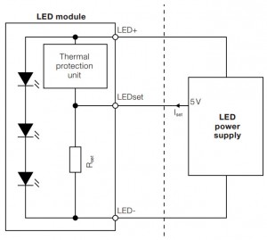
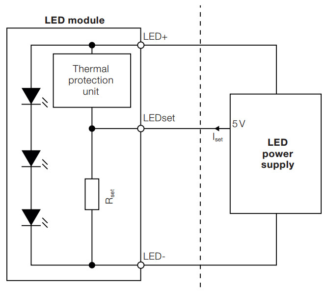
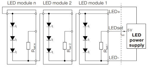
Called LEDset1 edition1.0, it is a three wire interface (see diagram): power, ‘Iset’ and a return for both. The specification also allows for separate returns for main and set currents to avoid setting errors due to return voltage drops.
Iset has nothing to do with dimming. It is provided so that the LED module can indicate its maximum working current to the driver. It does this by drawing Imax/1,000 from Iset.
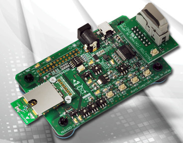
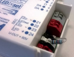
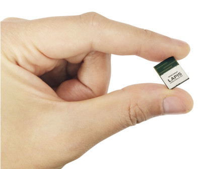
In detail, the PSU is required to hold 5V on Iset, and a resistor in the LED module or separately connected to the PSU (see photo) draws the setting current. The driver then provides 1,000x this current to the LEDs.
The only time any modulation of Iset is allowed is if the LED module is over-heating, when it is permitted to reduce its own supply current by reducing Iset.
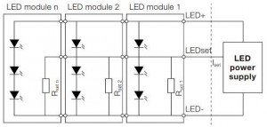
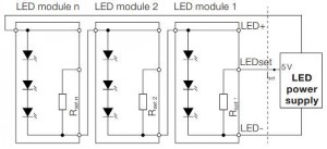
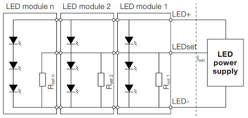
 LEDset1 works with paralleled LED module providing voltage requirements match, and series configurations providing current requirements match (see diagrams below).
What about dimming?
At this point is is useful to know LED lighting power supplies are also known as ‘drivers’ and ‘electronic control gear’ (ECG) – and occasionally as ‘ballasts’ following fluorescent lighting practice.
“The LEDset1 information interface is not meant to be used for dimming. It is focusing on setting the drive current for nominal 100% operation and enables thermal de-rating,” said MD-SIG. “The reason is that the LED control gear may respond to changes in the setting current at a low rate. Accordingly, the scaled output current may lag the setting current by many seconds.” LEDset1 allows up to 10s for response.
Dimming through a separate interface to the driver is under discussion for a future LEDset specification, as is colour steering.
The official names of the three terminals are: LED+, LEDset and LED-. The optional Iset return is ‘GRNset’.
LED module and driver must be marked accordingly, and recommended wire colours are: red, white, black and black respectively.
Although LEDset1 specifies a universal analogue signalling protocol, it does not cover the matching of driver output voltage and current capability with LED module needs.
A MD-SIG power interface specification is work in progress.
 “The power interface specification describes driving capabilities like voltage, current and power ranges of LED control gears and respective LED module operating requirements,” said the SIG. “It simplifies matching and comparing output and input parameters with harmonised terms and definitions.”
Osram has already adopted LEDset edition 1.0 as its own LEDset Gen2 specification. Osram’s first generation LEDset was a similar but incompatible system. The firm is allowing set resistors from 50kΩ to 1kΩ (100mA-5A ILEDmax). Osram’s specification includes NTC and PTC thermistor circuits to implement thermal protection feedback.
What aboug Zhaga
Zhaga Consortium is a separate LED lighting standardisation body, sharing significant members with MD-SIG. Although covering some electrical issues, it mainly concerns itself with mechanical interchangeability – allowing luminaire makers to pick physically-compatible LEDs, lenses, reflectors, connectors and heatsinks from various component makers.
 Until recently, Zhaga has not considered the electrical interface between driver and LED module (LLE – LED light engines in Zhaga’s nomenclature) – instead considering LED module and driver as a single, if sometimes distributed, electrical entity.
Recognising industry’s wish to separately mix and match driver and LED module, Zhaga has now introduced Book 13 (Zhaga specifications are called ‘Books’). Book 13 adopts MD-SIG’s electrical scheme alongside mechanical interchangeability requirements developed by Zhaga.
“MD-SIG defines standardised interfaces between LED modules and LED drivers that, when used in combination with specifications created by the Zhaga Consortium, will enable manufacturers of LED luminaires to interchange LED modules and LED drivers made by different manufacturers.” said MD-SIG.
A complete list of MD-SIG members is: BAG, Helvar Osram, Panasonic/Vossloh Schwabe, Philips, TCI, Zumtobel/Tridonic. It is administrativley under the wing of IEEE-ISTO in New Jersey.
steve bush


 Applications in health and fitness devices are expected. Enabled profiles include: HRP (heart rate), HTP (health thermometer), BLP (blood pressure), GLP (glucose), BAS (battery service) and DIS (device information).