Author Archives: richard wilson

PXI fault insertion switch module goes differential

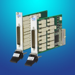
Pickering Interfaces is expanding its range of PXI Fault Insertion switch modules with two cards designed for use with differential serial interfaces.

PXI fault insertion switch module goes differential

PXI fault insertion switch module goes differential

The first differential PXI module (model 40-200) is designed for lower data rate serial interfaces such as CAN and FlexRay.

A higher bandwidth switch module (model 40-201) is designed for higher data rate serial interfaces such as AFDX and 1000BaseT Ethernet.

The modules can be used to provide fault connections that include data paths open, data paths shorted together, and data paths shorted to externally applied faults such as power supplies and ground.

The software driver defaults to a protective mode where conflicting faults are prevented to avoid accidentally shorting unintended paths, such as power to ground. A separate mode allows complete freedom in setting fault patterns.

Connections are available on a easy to use 78-way D connector and are supported by Pickering’s range of general purpose (non-differential) cable and connector options.


Richard Wilson

PXI fault insertion switch module goes differential

Pickering Interfaces is expanding its range of PXI Fault Insertion switch modules with two cards designed for use with differential serial interfaces.

PXI fault insertion switch module goes differential

PXI fault insertion switch module goes differential

The first differential PXI module (model 40-200) is designed for lower data rate serial interfaces such as CAN and FlexRay.

A higher bandwidth switch module (model 40-201) is designed for higher data rate serial interfaces such as AFDX and 1000BaseT Ethernet.

The modules can be used to provide fault connections that include data paths open, data paths shorted together, and data paths shorted to externally applied faults such as power supplies and ground.

The software driver defaults to a protective mode where conflicting faults are prevented to avoid accidentally shorting unintended paths, such as power to ground. A separate mode allows complete freedom in setting fault patterns.

Connections are available on a easy to use 78-way D connector and are supported by Pickering’s range of general purpose (non-differential) cable and connector options.


Richard Wilson

Mentor tools up 64-bit ARM processors at AMD

Mentor tools up 64-bit ARM processors at AMD

Mentor tools up 64-bit ARM processors at AMD

Mentor Graphics is offering embedded Linux tools for AMD’s 64-bit ARM processors as part of its Embedded Sourcery CodeBench Lite tool set.

The two companies have been working together for a year creating an ecosystem open-source, embedded C/C++ development tools for AMD’s 64-bit processors based on the ARMv8 core.

The microcontrollers can be designed into RTOS, bare metal, and Linux-based applications.

Sourcery CodeBench is an IDE based on Eclipse, the Eclipse C/C++ development tools and compilers, and GNU tool chain, including an assembler, linker, runtime libraries, and source-level and assembly-level debuggers.

3dc99de

Charlene Marini, v-p marketing, ARM

“AMD and Mentor Graphics’ support of the ARMv8-A embedded Linux ecosystem will shorten advanced system development cycles, reduce risk and improve product reliability,” said Charlene Marini, vice president of marketing, Embedded Segments, ARM.

The ARMv8 architecture is ARM’s first 64-bit processor architecture which is compatible with existing 32-bit software.

The current ARM processors supporting the ARMv8-A architecture are the Cortex-A72, Cortex-A57 and Cortex-A53 processors.


Richard Wilson

How to meet military EMC regulations

Pete Dorey

Pete Dorey

The European EMC defence standard 59-411 can help with achieving electromagnetic compatibility for COTS military systems, writes Pete Dorey.

The electromagnetic compatibility (EMC) risk assessment process described in Defence Standard 59-411 contains four key steps to assess whether any protection, such as shielding racks and filters, is needed to reduce equipment susceptibility to harsh defence electromagnetic environments and to enhance compatibility with sensitive systems such as military radio.

Define the electromagnetic environment

Once this environment definition is known, the adequacy of the military off-the-shelf/commercial off-the-shelf (MOTS/COTS) EMC performance can be evaluated.

The target electromagnetic environment is usually specified in a User Requirement Document (URD) or System Requirement Document (SRD), and is likely to be one of the default electromagnetic environments described in Def Stan 59-411, such as a ship below-decks environment.

However, it may also be specified for a unique purpose, to ensure compatibility with specified systems, or tailored to a specific environment.

Evaluation of EMC compliance

All non-exempt MOTS/COTS equipment must carry the CE mark of European directives, but its presence alone is not enough to identify levels of EMC performance to which the equipment must comply. This must be identified from the manufacturer’s EU Declaration of Conformity, test report, certificate or specifications.

It is best practice that a copy of the EMC test report or certificate is obtained to confirm the limits applied during testing, in order to ensure the equipment’s suitability for military use. However, obtaining the evidence of EMC compliance is often a major challenge.

Using the guidance in Def Stan 59‑411, a ‘gap analysis’ process can be used to determine whether the MOTS/COTS EMC compliance evidence is more or less stringent than the Def Stan 59-411 test limit. Any shortfalls identified also help to specify the degree of additional protection that is required, such as shielding or filter attenuation.

During this process, it is imperative to identify the test methods and account for them as part of the comparison. This can be a time consuming, costly and complex exercise, so the use of specifically designed gap analysis tools is recommended.

Functional criticality

The risks identified during the gap analysis process must now be compared to the criticality of the equipment and platform environment impact in which the COTS/MOTS equipment will be used.

If any unacceptable risks are identified, they must be mitigated. For example, if the equipment has a critical function itself, adequate immunity is required. If the equipment is co-located with other sensitive critical equipment, adequate emission control is required.

Once the functional criticality process has determined the unacceptable risks, they must then be mitigated.

Mitigation of unacceptable risk

There are two options for risk mitigation, either:

• Retest the MOTS/COTS equipment to determine compliance with Def Stan 59-411. This is technically a good approach, as any additional protection can be properly specified and over‑protection will be avoided. However, the disadvantage is the cost of the additional required testing.

• Remedial re-design can be achieved by adding the appropriate protection ‘barriers’ to reduce the coupled RF fields or currents that the equipment could be exposed to, or could emit, to below the levels it was originally required to meet.

Many manufacturers now offer suitable RF shielded racks and enclosures for this purpose, which allow the MOTS/COTS equipment to be housed without modification therefore preserving the validity of its CE marking. Additional filters and transient protection can also be accommodated within the enclosure. If the equipment itself is modified to achieve EMC, it is considered to have become ‘modified off the shelf’ equipment and needs to meet the EMC Directive with CE marking as a ‘new apparatus’ in its own right.

Something that could be overlooked is that the current UK EMC regulations (SI 2006 No.3418) implementing the EMC Directive 2004/108/EC do not have a specific exemption for defence equipment, whereas the previous regulations did, under Article 346 of the Treaty of the European Community.

This has led to some confusion among designers and manufacturers, with some presuming that a ‘blanket’ exemption applies to military equipment.

However, the applicability of CE marking to military equipment was clarified by the European Commission in April 2012 with the statement: “Equipment which falls within the scope of the Radio & Telecommunications Terminal Equipment Directive, EMC Directive or Low Voltage Directive, shall be compliant with the applicable Directive(s) and bear CE marking.”

Defence contractors must therefore ensure that any manufacturers or suppliers they use understand and comply with these rules.

Member states can exclude defence equipment from the scope of European Union procurement regulations and Directives pursuant to Article 346 (ex.296) of the Treaty on the Functioning of the European Union on the basis of the protection of national security interests.

This is not a decision for the manufacturer. Further guidance on the compliance of military equipment with the EMC Directive was published by CENELEC in report TR50538 in 2010.

In April 2016, a new EMC Directive 2014/30/EU and EMC Regulations will come into force, but do not affect the requirement for military equipment. Applying the EMC Directive to defence equipment requires careful management to avoid unnecessary duplication of compliance-testing – once for Def Stan 59-411 and once for CE marking, which will incur additional costs.

However, testing can be minimised by using the gap analysis process to establish in the technical documentation the equivalence between Def Stan 59-411 and the MOTS/COTS standards. This in itself can be a time consuming and costly exercise and often takes users away from their core expertise or comfort zone.

Due to the complexity of performing gap analysis, such a partner could offer a low risk, and ultimately low cost solution to deal with defence EMC requirements. It will ensure that the resulting products are legally placed on the market and acceptable for delivery, particularly for high-value projects.

Writer is Pete Dorey, a principal EMC consultant at product testing and certification organisation, TÜV SÜD Product Service

Richard Wilson

How to meet military EMC regulations

Pete Dorey

Pete Dorey

The European EMC defence standard 59-411 can help with achieving electromagnetic compatibility for COTS military systems, writes Pete Dorey.

The electromagnetic compatibility (EMC) risk assessment process described in Defence Standard 59-411 contains four key steps to assess whether any protection, such as shielding racks and filters, is needed to reduce equipment susceptibility to harsh defence electromagnetic environments and to enhance compatibility with sensitive systems such as military radio.

Define the electromagnetic environment

Once this environment definition is known, the adequacy of the military off-the-shelf/commercial off-the-shelf (MOTS/COTS) EMC performance can be evaluated.

The target electromagnetic environment is usually specified in a User Requirement Document (URD) or System Requirement Document (SRD), and is likely to be one of the default electromagnetic environments described in Def Stan 59-411, such as a ship below-decks environment.

However, it may also be specified for a unique purpose, to ensure compatibility with specified systems, or tailored to a specific environment.

Evaluation of EMC compliance

All non-exempt MOTS/COTS equipment must carry the CE mark of European directives, but its presence alone is not enough to identify levels of EMC performance to which the equipment must comply. This must be identified from the manufacturer’s EU Declaration of Conformity, test report, certificate or specifications.

It is best practice that a copy of the EMC test report or certificate is obtained to confirm the limits applied during testing, in order to ensure the equipment’s suitability for military use. However, obtaining the evidence of EMC compliance is often a major challenge.

Using the guidance in Def Stan 59‑411, a ‘gap analysis’ process can be used to determine whether the MOTS/COTS EMC compliance evidence is more or less stringent than the Def Stan 59-411 test limit. Any shortfalls identified also help to specify the degree of additional protection that is required, such as shielding or filter attenuation.

During this process, it is imperative to identify the test methods and account for them as part of the comparison. This can be a time consuming, costly and complex exercise, so the use of specifically designed gap analysis tools is recommended.

Functional criticality

The risks identified during the gap analysis process must now be compared to the criticality of the equipment and platform environment impact in which the COTS/MOTS equipment will be used.

If any unacceptable risks are identified, they must be mitigated. For example, if the equipment has a critical function itself, adequate immunity is required. If the equipment is co-located with other sensitive critical equipment, adequate emission control is required.

Once the functional criticality process has determined the unacceptable risks, they must then be mitigated.

Mitigation of unacceptable risk

There are two options for risk mitigation, either:

• Retest the MOTS/COTS equipment to determine compliance with Def Stan 59-411. This is technically a good approach, as any additional protection can be properly specified and over‑protection will be avoided. However, the disadvantage is the cost of the additional required testing.

• Remedial re-design can be achieved by adding the appropriate protection ‘barriers’ to reduce the coupled RF fields or currents that the equipment could be exposed to, or could emit, to below the levels it was originally required to meet.

Many manufacturers now offer suitable RF shielded racks and enclosures for this purpose, which allow the MOTS/COTS equipment to be housed without modification therefore preserving the validity of its CE marking. Additional filters and transient protection can also be accommodated within the enclosure. If the equipment itself is modified to achieve EMC, it is considered to have become ‘modified off the shelf’ equipment and needs to meet the EMC Directive with CE marking as a ‘new apparatus’ in its own right.

Something that could be overlooked is that the current UK EMC regulations (SI 2006 No.3418) implementing the EMC Directive 2004/108/EC do not have a specific exemption for defence equipment, whereas the previous regulations did, under Article 346 of the Treaty of the European Community.

This has led to some confusion among designers and manufacturers, with some presuming that a ‘blanket’ exemption applies to military equipment.

However, the applicability of CE marking to military equipment was clarified by the European Commission in April 2012 with the statement: “Equipment which falls within the scope of the Radio & Telecommunications Terminal Equipment Directive, EMC Directive or Low Voltage Directive, shall be compliant with the applicable Directive(s) and bear CE marking.”

Defence contractors must therefore ensure that any manufacturers or suppliers they use understand and comply with these rules.

Member states can exclude defence equipment from the scope of European Union procurement regulations and Directives pursuant to Article 346 (ex.296) of the Treaty on the Functioning of the European Union on the basis of the protection of national security interests.

This is not a decision for the manufacturer. Further guidance on the compliance of military equipment with the EMC Directive was published by CENELEC in report TR50538 in 2010.

In April 2016, a new EMC Directive 2014/30/EU and EMC Regulations will come into force, but do not affect the requirement for military equipment. Applying the EMC Directive to defence equipment requires careful management to avoid unnecessary duplication of compliance-testing – once for Def Stan 59-411 and once for CE marking, which will incur additional costs.

However, testing can be minimised by using the gap analysis process to establish in the technical documentation the equivalence between Def Stan 59-411 and the MOTS/COTS standards. This in itself can be a time consuming and costly exercise and often takes users away from their core expertise or comfort zone.

Due to the complexity of performing gap analysis, such a partner could offer a low risk, and ultimately low cost solution to deal with defence EMC requirements. It will ensure that the resulting products are legally placed on the market and acceptable for delivery, particularly for high-value projects.

Writer is Pete Dorey, a principal EMC consultant at product testing and certification organisation, TÜV SÜD Product Service

Richard Wilson
ST creates ecosystem for STM32L4 ARM Cortex-M4 MCUs

STMicroelectronics has created a design ecosystem with development boards and software for its STM32L4 microcontrollers.

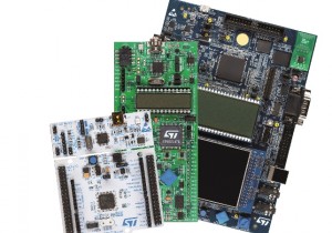
This includes a budget board for engineers, students, and hobbyists called STM32 Nucleo board (NUCLEO-L476RG) which costs $10.32.

PR_STM32L4

Three STM32L4 MCU development boards

The Nucleo board has Arduino Uno headers for adding shields and its own ST-Link debugger/programmer removes the need for a separate debug probe.

The STM32L4 MCU is notable for an 80MHz ARM Cortex-M4 core with DSP extensions and floating-point unit.

There is also a full spec Evaluation Board (STM32L476G-EVAL) priced at $289 and the $19.90 Discovery Kit (STM32L476G-DISCO) which incorporates a MEMS microphone and motion sensors, along with DAC, 96-segment LCD, and 16Mbyte QSPI flash memory.

The Discovery and Nucleo boards both provide direct access to mbed online tools.

Software support includes the STM32CubeMX configurator and initialization-code generator.

MCU-specific software provides a Hardware Abstraction Layer (HAL), application examples, and new Low-Layer APIs.

“The APIs can be used in parallel with the HAL and simplify migrating projects developed with STM32 standard peripheral libraries into the STM32Cube environment,” said the supplier.


Richard Wilson

IoT gets a new wireless technology backed by Intel, Nokia and Ericsson

IoT has a new wireless technology and it has influential supporters in Intel, Nokia and Ericsson.

It is a narrowband version of 4G LTE, dubbed NB-LTE, which has been created just for the needs of the internet-connected devices and sensors which will make up the internet of things (IoT).

Nokia supports NB-LTE

Nokia supports NB-LTE

Not everyone supports the technology. Huawei of China is not a friend of NB-LTE and it believes there are better ways to adapt existing networks.

Unlike smartphones which require as large a bandwidth in the radio channel for downloading big data files such as video and music, IoT devices will only transmit small amounts of data.

But the main requirements of an IoT wireless protocol is that it must not require a big data processing function so the IoT devices can be low power and small.

The advantage NB-LTE has is that it will build on the proliferation of 4G LTE networks, requiring only an upgrade to existing infrastructure to support IoT services.

“Cellular networks already cover 90 percent of the world’s population so it makes sense to leverage this global footprint to support and drive IoT adoption through the standardisation of narrow-band LTE,”said Thomas Norén, head of radio product management, Ericsson.

Intel has said it will start offering first chips for narrow-band LTE in 2016.

The chip company will work with wireless network suppliers Nokia and Ericsson to support the upgrade of existing LTE networks with narrow-band LTE for the roll out of machine-to-machine communication and IoT services.

What other narrowband radio technologies could be used for IoT?

For short range wireless links mesh technologies such as Bluetooth and ZigBee will be used and even Wi-Fi extensions. But it may not be easy or even possible to scale these up for wide-area coverage.

“We believe in building an ecosystem around NB-LTE to speed up the take-up of the Internet of Things,” said Stephan Litjens, vice president, portfolio strategy & analytics, Nokia Networks.

Richard Wilson

TSMC uses Cadence design flow for 10nm finfet chip designs

TSMC has created a 10nm custom design reference flow for tools supplied by Cadence, and it is working on first commercial 10nm finfet chip designs.

TSMC uses Cadence design flow for 10nm finfet chip designs

TSMC uses Cadence design flow for 10nm finfet chip designs

The importance elements in the design of 10nm chips are: creating FinFET arrays which avoid density gradient effects and being able to handle multi-patterning designs.

The tools must also have the capability to extract and analyse real-time parasitics and electromagnetic violations during design implementation.

Cadence’s digital, custom/analogue and signoff tools have achieved certification from TSMC for V0.9 of its 10nm process and are expected to achieve V1.0 completion by Q4 2015.

The target for will be designing first 10nm smartphones and tablets application processors and high-end servers.

The Cadence tools in the flow include: Virtuoso custom IC advanced-node platform, Spectre simulation tool, physical verification software, Innovus, Quantus and Tempus timing signoff.

Dr. Chi-Ping Hsu, senior vice president and chief strategy officer for EDA at Cadence said: “We are now actively working with customers on 10nm designs and seeing great successes.”

According to Suk Lee, TSMC senior director, design infrastructure marketing division, the reference flows in both digital and custom design can “help customers reduce iterations and improve predictability while bringing their products to the market.”

See alsoImec and Synopsys work on 10nm finfet chip design


Richard Wilson