Author Archives: richard wilson

Chip suppliers focus on high resolution audio

Tensilica Audio IP

Tensilica Audio IP

High resolution audio is the music industry’s next focus, according to a new industry report, which also said that ‘lossless’ streaming subscriptions are expected to account for almost 25% of all music subscriptions by 2020.

But this does not mean the lower quality MP3 music file format is going to be replaced anytime soon.

“Amazingly, the MP3 music format is 25 years old, and it still has an important part to play in today’s music landscape. However, because it compresses the music file for easier storage and internet transfer, the music quality invariably suffers,” said Peter Cooney, Principal Analyst & Director of SAR Insight & Consulting.

As broadband coverage widens and mobile download speeds increase thee will be an opportunity for higher resolution audio.

According to the latest report from SAR Insight & Consulting, called: ‘High Resolution Audio: Creating Opportunities Across the Audio Ecosystem; State of the Industry Today and Future Market Growth’ the music industry as a whole has been slow to embrace HRA, but the link up between the Consumer Electronics Association, The Digital Entertainment Group, Japan Audio Society and major music labels, such as Sony Music Entertainment, Universal Music Group and Warner Music Group in 2014 to define and promote high resolution audio formats through formal definitions for master quality sources, was a major step forward.

“There is a strong incentive for the music industry to drive consumer awareness and, therefore, increase interest in HRA music as this can be used to reinvigorate the download market, help increase prices for a premium product, and help to drive premium streaming services,” said Cooney.

HRA also has the support of major artists, such as the Foo Fighters who, earlier this year, teamed up with Sony Music to promote the lossless format. But there are still barriers to market.

“Consumers, particularly younger people, have become increasingly accustomed to or have grown up only listening to compressed audio. This is perhaps the most difficult hurdle to overcome for the music industry as a whole if it is to drive HRA to the mass market,” said Cooney.

Richard Wilson

Five million Raspberry Pi’s is a Sony UK success story

Five million Raspberry Pis have been manufactured by Sony UK Technology Centre in Wales since the educational computer was launched three years ago.

Five million Raspberry Pi's is a Sony UK success story

Five million Raspberry Pi’s is a Sony UK success story

During the three year relationship the site has made five different models of the Pi, has increased its production from 10,000 units per week to 80,000 units.

“The Raspberry Pi, is a fantastic example of UK innovation, design and engineering, at its best,” said Steve Dalton OBE, managing director of Sony UK Technology Centre.

Sony has also resulted in the employment of 70 new staff  and 30 more will be recruited by the end of the year.

Eben Upton, Co-Founder of The Raspberry Pi said:

“Raspberry Pi is a British product, created by British engineers, that has found a huge global market.  South Wales has a long tradition of manufacturing, and we are very pleased that the success of Raspberry Pi has secured new, skilled jobs in the area. Global success can be transformative within local communities, and we’re proud to be part of that here in Pencoed.”

The product which has been developed by non-profit Raspberry Pi Foundation, is designed to stimulate young people’s interest in computer programming and electronics, but it has been hugely popular with hobbyists and developers.

Pencoed-based Sony UKTEC is producing the Raspberry Pi for the its two distributors, element14 and RS Components.

Claire Doyle, Global Head of Raspberry Pi at element14, said:

“We’re delighted to have been able to make such a success of the Raspberry Pi’s UK manufacture.  Working with Sony’s UK Technology Centre team in Pencoed has been an easy decision from the start. By making Raspberry Pi in Wales we’re able to ensure great quality and exceptionally competitive pricing, and have been able to benefit from a really great business relationship.”

To celebrate the milestone, Sony UKTEC welcomed Jo Johnston MP, Minister of State for Universities and Science for UK Government, Jonathan Hardie, Global Head of Manufacturing from leading manufacturer and distributor element14 and Phillip Colligan and Eben Upton from the Raspberry Pi Foundation.

See alsoVideo -How they make Raspberry Pi in the UK

Richard Wilson

Failure should not be an option for Al capacitor

The aluminium capacitor is a common feature of power supplies, since it is the most suitable for functions such as energy storage and low- or high-frequency filtering. Unfortunately, aluminium capacitors are also often the components most prone to failure: the operating lifetime of an aluminium capacitor will tend to determine the operating lifetime of the entire power supply, writes Marcin Chelminski of Future Electronics.

This means that designers have to take great care when calculating the parameters of aluminium capacitors to choose the most appropriate part for their device.

The choice of capacitor also has to balance cost against performance: after magnetic components, aluminium capacitors are often the most expensive passive components in a power supply.

The reliability of an aluminium electrolytic capacitor is generally measured by its expected life in use.

Minor factors that affect their life include humidity, vibration and heat transmitted through the printed circuit board patterns.

But three other factors have a greater effect on useful life, these are: ambient temperature, ripple current and applied voltage.

The basic application guidelines for aluminium capacitors say that operating temperature, applied ripple current and applied voltage should always stay below the specified maximum allowable values.

But these guidelines do not provide enough information to enable power‑supply designers to optimise for long operating life.

For this, they need to estimate the effect on lifetime of variations in operating conditions within the maximum allowable limits.

By accurately estimating the effect of changes in operating conditions, designers can extend the lifetime of aluminium capacitors in any given application.

The latest generation of dedicated power-supply capacitors, which benefit from the most recent advances in design and materials, can offer long lifetimes of up to 15 years in a surprisingly wide range of operating conditions without incurring the cost ultra high reliability capacitors.

Aluminium capacitor failure modes

Aluminium capacitors implement a variety of functions, depending on their position in the circuit.

As an input buffer in an AC-DC converter, an aluminium capacitor provides energy when the mains input voltage is too low, or stores energy when it is too high.

As an output buffer, an aluminium capacitor performs filtering and acts as a current sink for an inductor.

In operation, these capacitors can fail in a number of ways:

  • catastrophic failure occurs when the capacitor completely breaks down, due to a short or open circuit.
  • degradation occurs when the capacitor continues to function, but its performance has deteriorated to some extent.

In the case of degradation, for instance, the device’s capacitance might fall over time. Whether the change in value is acceptable or not depends on the requirements of the application. If it is unacceptable, the device has effectively failed.

A short circuit between the electrodes can be caused mechanically, by shock, vibration or stress on the leads.

It can also be caused electrically, by the application of a pulse current or voltage which exceeds the rated maximum value.

There can be various causes of an open circuit. For instance, if the capacitor is subjected to too high a force at the time of mounting, the connection between the lead wire and the tab could be twisted or distorted.

High temperature is also dangerous, either by operating at a temperature above the rated maximum, or through exposure to excessive heat transmitted through the circuit board’s tracks, which vaporises the capacitor’s electrolyte.

Similarly, exposing the capacitor to excessive ripple current causes its internal temperature to rise, drying the electrolyte.

A fall in capacitance and increased power losses due to high equivalent series resistance (ESR) occur when:

• a reverse voltage is continuously applied

• the capacitor is subjected to a very high number of charge/discharge cycles

• applied current exceeds the maximum rated ripple current.

Optimise for conditions

Standard load life test limits applied to aluminium capacitors (at their rated voltage and maximum rated temperature) typically measure the elapsed time until the capacitor suffers a 20% or 30% decrease in capacitance from its initial value, a 200% or 300% increase in loss tangent (a measure of the power losses attributable to the dielectric), or a 200% increase in leakage current – whichever occurs first.

These standard limits provide a quick but rough means of comparing the performance of competing devices. But they do not necessarily reflect the requirements of any given application.

So to optimise the lifetime/cost trade-off and find the best possible capacitor for a specific power supply, the designer must calculate the expected life of capacitors under evaluation in the expected operating conditions of the application.

Before doing so, it is worthwhile considering how the operating conditions of the power supply might be modified so as to minimise the hazard to any aluminium capacitors on the board.

The electrical characteristics of aluminium electrolytic capacitors are more sensitive to temperature than those of other types of capacitors, because the properties of the liquid electrolyte in aluminium capacitors, (such as conductivity and viscosity) are strongly affected by temperature.

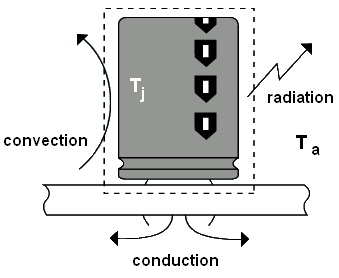
To reduce the device’s exposure to high temperatures, the designer needs to understand the flow of thermal energy through it (Figure 1).

Inside the dotted line, all the materials are at the device’s junction temperature (Tj); outside the dotted line is the ambient temperature (Ta).

The heat generated inside the dotted line is carried outside it by convection, radiation and conduction.

TAP1422_capacitors_Fig 1

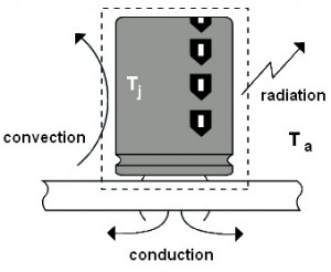
Figure 1: the three ways in which heat escapes from a power supply’s capacitor

If the designer can implement a means to improve the heat flow out of the capacitor, its expected operating lifetime will be extended.

Indeed, according to the Arrhenius theory, the life of an aluminium capacitor doubles with every 10°C fall in ambient temperature.

Such a fall has a direct effect on the designer’s lifetime calculation when the heat generated by resistive losses (for instance, in timing circuits) is negligible.

The basic method of cooling a capacitor is to mount it in free space. The natural circulation of air around the device will provide sufficient cooling for most applications.

If this is not enough, a heat sink will increase the flow of heat from the device. The most common type of heat sink is an aluminium extrusion attached to the closed end of the capacitor. An alternative is a semi-circular extrusion designed to clamp to the case of the capacitor.

Whichever capacitor is used in a power supply, the designer can ensure that the device survives for its average rated lifetime by regulating the temperature, ripple current and applied voltage to within the manufacturer’s specified limits.

Marcin Chelminski, central applications engineer, Future Electronics (Poland)


Richard Wilson

New head of Digi-Key talks to Electronics Weekly

Dave Doherty, the new president and chief operating officer of online distributor Digi-Key talks to Electronics Weekly about how the internet is changing the way engineers source components and the hype around IoT.

Q: What do you see as the biggest challenges facing the electronics distribution sector?

Dave Doherty

Dave Doherty

Dave Doherty : Adapting to the reality of a global economy.  This is far different from having companies incorporating around the globe but operating regionally.  To date, customers are moving faster with their supply chain needs and suppliers are struggling to keep pace with their regional legal entity structures operating autonomously.  In addition, there are dynamic currency fluctuations in play in this global economy.

Q: How have you seen the customer landscape evolve in the past five years?  Where do you see it going in the next few years?

Dave Doherty : Customers are looking for instantaneous access to information and they are more than willing to self-serve, in fact many prefer it.  Our B2B customers’ response time to their end customers continues to shrink, requiring us to offer solution based products and not just parts.  There are still the mega-volume consumer aimed products such as mobile devices but there is an even larger proliferation of high-mix/low volume requirements in areas like industrial, medical, IoT, etc.

Q: How do you see the evolution of technology (IoT, 3D Printing, Big Data, etc.) impacting the demand from the customer?

Dave Doherty: Our industry loves hype and attributing the latest and greatest buzz words to trends.  The hottest of late, IoT, is not a recent phenomenon.  Sensor activity has been accelerating for some time, as has a movement towards connectivity and a lowering price point for microcontrollers all the while accelerating a movement towards mechatronics.

Our industry (consumers, suppliers, distributors) has been very respectful of our social and environmental responsibilities (i.e.  RoHS, NoPB).  These trends will only contribute as we balance the need to push and develop cost effective technologies in a socially responsible way.  Our industry in an example of global ingenuity at its finest.  From a cost/performance perspective, I’m hard pressed to think of another industry that could keep pace.

Q: How are customer demands for design help changing and evolving?  What are your key market segments?  How is that evolving?

Dave Doherty: The need for 24/7 technical and customer service support is profound.  The desire for web chat activities instead of traditional tech support calls.  We are seeing more activity for kits, development boards, modules, reference designs and other solution oriented products.

We don’t necessarily see a change in direction for the supply chain, but rather an acceleration of our response to our customers.  You will see more electronic data interchange connecting our systems through legacy means such as EDI and emerging alternatives such as APIs.

Q: What are your greatest concerns from a supply chain perspective for the remainder of the year?

Dave Doherty: We are in the segment of the supply/demand cycle in which product is generally available with low lead times.  This tends to drive lower customer volumes offset with increased frequency to minimise their inventory carrying costs.  These cycles tend to flip fairly quickly, through either a real or perceived disruption to the supply chain, inevitably accentuated by an emotional over-reaction that stretches lead-time and increases supply chain disruptions.  We cannot become complacent or lose sight of our role in the process.

Richard Wilson

AMS extends analogue foundry business with scalable process

AMS continues to invest in and extend its analogue foundry business.

AMS Fab B analogue foundry, top right

AMS Fab B analogue foundry, top right

Last month the Austrian semiconductor maker announced a government partnership in the US to build a new 8-inch fab in New York.

The company has now added to its foundry offering in Europe with an enhancement of its 0.35µm high voltage CMOS process which will offer more dies per wafer.

Called its H35 process, it makes use of voltage scalable NMOS and PMOS transistors to lower on-resistance and so reduce die area per device.

According to AMS:

“Using an optimized 30V NMOS transistor in power management applications instead of a fixed 50V transistor results in an area saving of approx. 50%.

“A 60V optimised NMOS device results in 22% less area when compared to a standard 120V NMOS transistor.”

Typical devices fabbed in this process include MEMS drivers, motor drivers, switches and power management ICs.

The foundry is automotive (ISO/TS 16949) and medical (ISO 13485) certified.

According to Markus Wuchse, general manager of ams’ Full Service Foundry division, the company ios one of the first foundry’s to offer scalable HV transistors.

“Our process design kit as well as our high voltage (HV) process expertise enable our partners to optimise their HV integrated circuits towards area and on-resistance, which immediately results in more dies per wafer,” said Wuchse.

The set of voltage scalable transistors including device layout generator (PCells), simulation models, verification rule decks for Calibre and Assura as well as documentation such as Design Rules and Process Parameters documents can be downloaded by registered users from the company’s secure foundry support server.


Richard Wilson

Capacitor reliability can be improved with the right materials

Although not all applications are safety critical or mission critical, reliability is still a vital consideration for many electronic products. Making informed choices at the component selection stage can help ensure the product will perform correctly over its intended lifetime, writes James Lewis of Kemet.

When choosing capacitors, properties such as volumetric efficiency, frequency stability, temperature rating or equivalent series resistance are often the primary factors that govern technology selection. In these cases, understanding factors affecting lifetime can help engineers ensure the product will deliver the required reliability.

On the other hand, a long operational lifetime may be a key requirement of the end product and ultimately may determine device selection.

Capacitor manufacturing processes such as screening, or processes to control the purity of materials or components, can provide a higher assurance of reliability that allows engineers to reduce the number of capacitors in-circuit and hence reduce solution size and cost without compromising reliability.

Capacitor Properties

Capacitors made with metallised polyester or polypropylene film, for example, are known to have a long operational life. High-voltage or high-temperature properties make these devices ideal for applications such as automotive electronics or lamp ballasts, while self-healing helps to overcome the effects of small impurities in the dielectric that can lead to short-circuit failures.
On the other hand, as these weaknesses heal the total available capacitance begins to drop and the equivalent series resistance (ESR) starts to rise. This ultimately governs the lifetime of the device. Using high-quality materials and dielectric-manufacturing processes can minimise defects leading to a slower rate of self-healing.

In alternative-energy applications, where low ESR is particularly desirable to minimise energy losses, it is possible to verify operational lifetimes of several decades, even when capacitors are operated at temperatures of 70°C or above.

Aluminium capacitors cover a number of different types of construction, each of which has very different lifetime performance. Wet-electrolyte capacitors, for example, have a well-defined and understood wearout mechanism. The electrolyte is mildly acidic, and will therefore degrade the dielectric over time.

On the other hand, the electrolyte also provides the oxygen necessary to re-grow the dielectric. This is why it is important to consider the “shelf-life” of a wet aluminium electrolytic capacitor that has not been powered—whether on a shelf or on a board.

Figure 1

Figure 1: X5R and X7R MLCCs combine nickel-based BME and doped barium titanate dielectric.

An interesting fact is that aluminium capacitors with a diameter of 30mm or more tend to have a more neutral electrolytic, rather than acidic, and so can have shelf-lives of two to four years at relatively moderate conditions. These figures, of course, vary by electrolyte used in each product family.

Solid “aluminium polymer” or “organic polymer” capacitors, on the other hand, have very different lifetime characteristics.
These devices have no electrolyte in the finished product. Instead the cathode is a solid conductive polymer material. This results in exceptionally long operational lifetime under rated conditions, which can be close to that of other solid capacitors.

Some datasheets describe the endurance of these types of devices in terms of properties such as capacitance change, ESR and appearance after 1,000 hours of operation.

It is important to note that the 1000 hours does not represent the capacitor’s operational life. Rather, this endurance testing is similar to the types of accelerated life testing that is typically used to qualify passive components.

As far as commercial-grade ceramic capacitors are concerned, the typical electrode system is a base metal electrode (BME) system, see figure 1, that primarily utilises nickel.

Compared to the earlier precious metal electrode (PME) systems, BME allows higher voltage stress capability. Popular X7R and X5R type dielectrics today are based on barium titanate, with additives such as manganese dioxide that coexist with the BME chemistry and prevent reduction of the dielectric by the firing processes applied to the capacitor during manufacture.

Improvements in dielectric composition have greatly increased the reliability and life of ceramics.

Tantalum Capacitor Reliability

Capacitors made with a tantalum dielectric have an exceptionally long operational life. Being a completely solid device, there is virtually no wear-out mechanism.

The most common failures for tantalum-based devices are so-called “turn on” failure. This can occur where a step-voltage is applied and the capacitor is able to draw a large initial current. This can activate a defect in the dielectric, which may cause device failure in the event that the dielectric cannot heal.

Polymer-tantalum devices benefit from a pronounced self-healing capability, and are known to be robust against this type of failure. Studies have shown that the lifetime of the capacitive elements may be in the hundreds or even thousands of years. This is likely to be considerably longer than the lifetime of other materials used in capacitor construction, such as epoxies.

Capacitor manufacturers tend to screen tantalum capacitors to identify potentially weaker devices, by applying tests such as voltage and current surge tests in a controlled sequence.

However, it is worth noting that the capacitors can be weakened by stresses introduced due to coefficient of thermal expansion (CTE) mismatches between constituent materials: hence reflow soldering conditions and the number of reflow cycles the capacitor is subjected to during final product assembly can affect the susceptibility to device failures.

On the other hand, the voltage rating of the device, relative to the applied voltage, can significantly influence capacitor lifetimes generally.

For this reason, recent development of polymer-tantalum capacitors has focused on realising higher voltage ratings such as 63V and higher for use with commonly used supply voltages such as 24V or the 28V avionics rail.

James C. Lewis is technical marketing director, Kemet.

Richard Wilson

Research cools solar cells for efficiency boost

Solar cells work more efficiently when they are cooled, but sitting the the sun all day, it is not always easy to achieve this.

Stanford School of  engineering graduate students Linxiano Zhu, Shanhui Fan, a Professor of Electrical Engineering  and grad student Aaswath Raman on Friday, October 10, 2014.  ( Norbert von der Groeben )

Stanford School of engineering graduate students Linxiano Zhu, Shanhui Fan, a Professor of Electrical Engineering and grad student Aaswath Raman on Friday, October 10, 2014. ( Norbert von der Groeben )

Researchers at Stanford University in the US have come up with a transparent overlay material that increases efficiency by cooling the cells even in full sunlight.

The material works by radiating heat away from the solar cells.

The researchers used a patterned silica material laid on top of a traditional solar cell. The material is transparent to the visible sunlight that powers solar cells, but captures and emits thermal radiation, or heat, as infrared rays.

According to Shanhui Fan, a professor of electrical engineering at Stanford: “Our thermal overlay allows sunlight to pass through, preserving or even enhancing sunlight absorption, but it also cools the cell by radiating the heat out and improving the cell efficiency.”

When it was tested on a custom-made solar absorber, a device that mimics the properties of a solar cell without producing electricity, it cooled the underlying absorber by as much as 23 degrees Fahrenheit.

“For a typical crystalline silicon solar cell with an efficiency of 20%, 23 deg F of cooling would improve absolute cell efficiency by over 1%, a figure that represents a significant gain in energy production,” said the researchers.

The same technology could be applied to other systems that need to be cool but also exposed to the visible spectrum of sunlight.

“Say you have a car that is bright red,” said Linxiao Zhu, co-first-author of the paper. “You really like that colour, but you’d also like to take advantage of anything that could aid in cooling your vehicle during hot days. Thermal overlays can help with passive cooling, but it’s a problem if they’re not fully transparent.”

That’s because the perception of color requires objects to reflect visible light, so any overlay would need to be transparent, or else tuned such that it would absorb only light outside the visible spectrum.

“Our photonic crystal thermal overlay optimises use of the thermal portions of the electromagnetic spectrum without affecting visible light,” Zhu said, “so you can radiate heat efficiently without affecting colour.”

The work by Shanhui Fan, a professor of electrical engineering at Stanford, research associate Aaswath P. Raman and doctoral candidate Linxiao Zhu is described in the current issue of Proceedings of the National Academy of Sciences.


Richard Wilson